 Placing New Provisional Axes
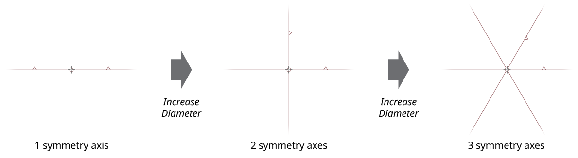
After the MirrorMe tool is selected, provisional symmetry axes will be drawn using thin maroon lines, with their center at the cursor location. As the cursor is moved around, the axes will follow. The number of axes (from 1 to 72) reflects the setting on the MirrorMe panel, and may be changed either by keying in a new value in the panel or by pressing the keys assigned to Decrease Diameter and Increase Diameter in the native Keyboard Shortcuts dialog (the left and right square bracket keys respectively, by default, for English language keyboards).
MirrorMe Basic Provisional Axes
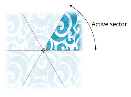
The active sector (the area in which any artwork is mirrored to fill the other sectors) is the sector indicated by two small triangles pointing inwards; it is also completely transparent, while the non-active (mirrored) quadrants are semi-transparent white while the axes are still provisional:
MirrorMe Active Sector
The axes are displayed as solid lines when the default setting Trim and Join Paths is enabled on the panel; otherwise, they are displayed with a long-dash-short-dash pattern.
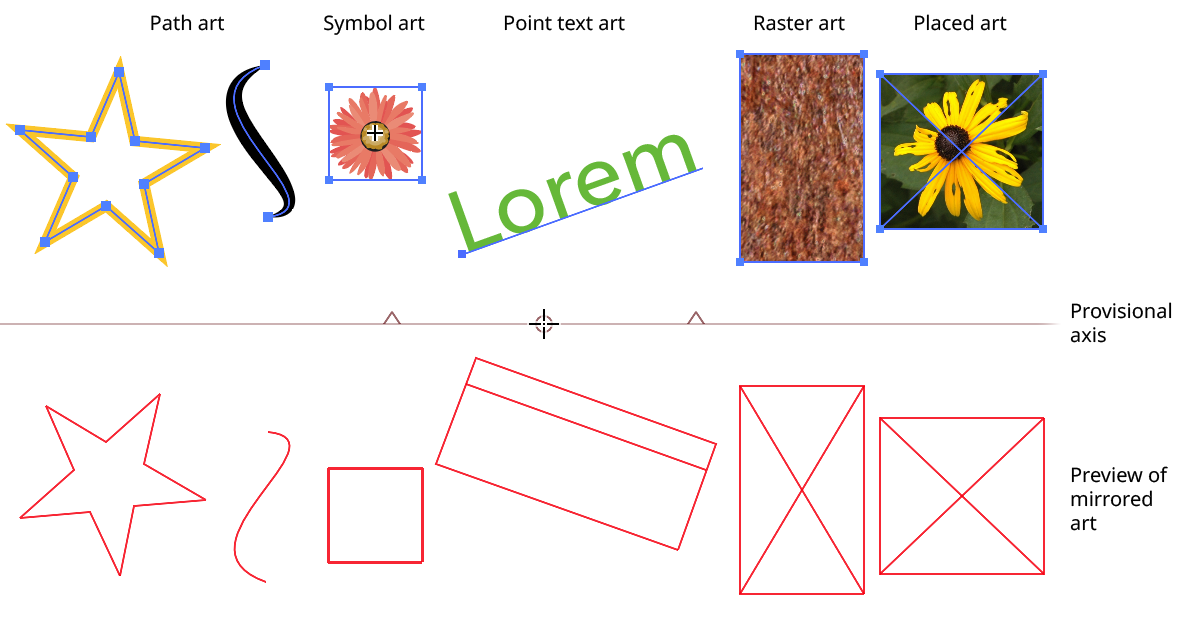
As the axes are moved, art which is at least partly in the active sector will have its mirrored positions previewed in real time using red wireframes. Paths are shown solely by their geometry (strokes and fills are not shown). Mesh objects are shown using their outside edge. Point text objects are shown by their bounds and include the baseline. Symbols are shown as quadrilaterals outlining their transformed bounds. Raster and placed art are similar, but with a “X” through them. Graph objects and guides are never mirrored.
MirrorMe Mirroring Preview
Which artwork is mirrored depends also on which of two modes is active on the panel. When Selected Artwork mode is active, only eligible artwork that is selected (on any layer) will be mirrored. Otherwise, with Entire Layer mode active, all eligible artwork on the current layer will be mirrored. The mode can be changed after the provisional axes have been placed.
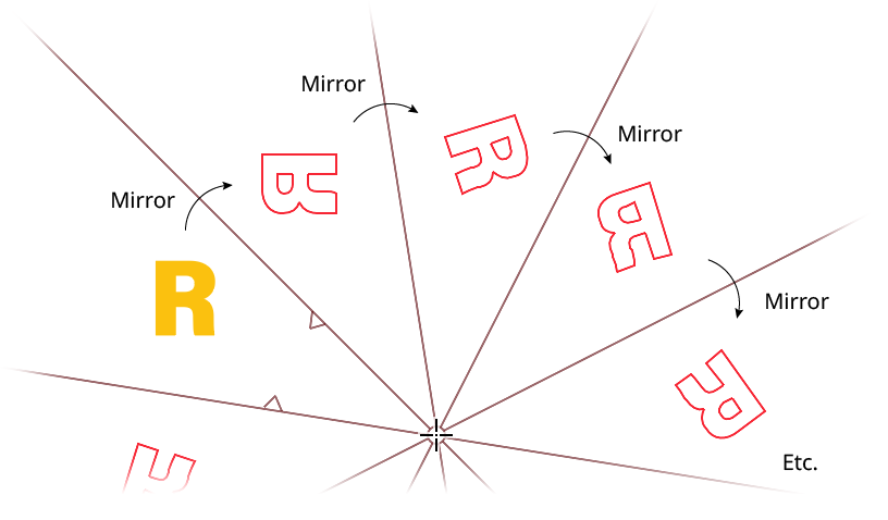
With a single axis, artwork is simply mirrored (reflected) across that axis, from the active half into the other half. When there are multiple axes, the mirroring proceeds from the active sector to adjacent sectors, mirroring across each succeeding axis. Thus, the art is reversed in alternate sectors:
MirrorMe Mirroring Across Multiple Axes
With the default Trim and Join Paths setting enabled, sections of paths which are outside the active sector are trimmed off and its mirrored pieces are joined together to form one or more continuous paths. The preview will faithfully show this:
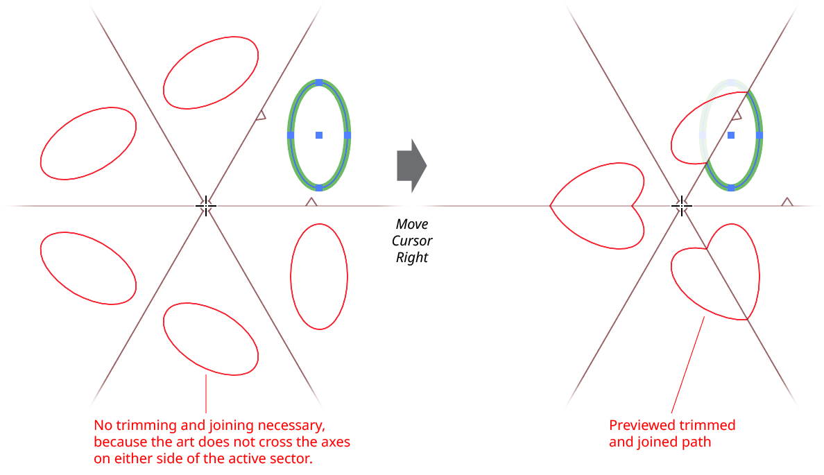
MirrorMe Mirroring Preview Trimming and Joining
The provisional axes will usually need to be rotated to put the active sector into the correct orientation. This may be done in several ways. A new rotation angle may be keyed into the panel. Or (unless the tool preference Initial Drag Positions Origin is enabled), the axes may be dragged, with the initial click also fixing the position of the axes origin. Finally, if the preference Change Active Sector With Shift is enabled, the Shift key may be tapped, which moves the active sector clockwise one position.
Once the mouse button has been clicked or the axes clicked-and-dragged, the axes are still provisional, and may be edited. Doubleclicking on either the small circle defining the axes origin point or on any axis will bring up a dialog which allows numerical control over the origin position, axes rotation, and number of axes (just as on the panel):
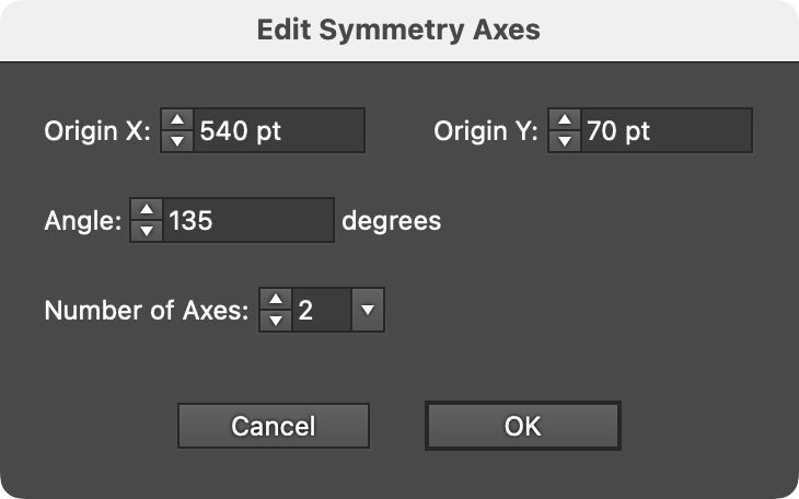
MirrorMe Edit Symmetry Axes Dialog
Dragging the axes origin point will reposition it. While dragging, there are several keypresses which may be utilized:
Shift: Constrains the origin’s movement to 45° increments around the general constrain angle.
Up Arrow/Down Arrow: Changes the number of axes.
1–9: Directly specifies the number of axes.
U: Temporarily disables Smart Guides, if they were enabled before the drag started.
T: Toggles the Trim and Join Paths setting.
Any axis (including the “virtual” axis which appears at the midpoint of the active sector) may be dragged to rotate all the axes. While dragging, there are several keypresses which may be utilized:
Shift: Constrains the axes rotation to angles that are 45° increments around the general constrain angle.
Command/Ctrl: Overrides the snapping that by default occurs when the dragged axis is perpendicular to a curved path segment (indicated with a small magenta dot); the axis will still snap to anchor points that are under the cursor.
Space: Moves the origin.
Up Arrow/Down Arrow: Changes the number of axes.
1–9: Directly specifies the number of axes.
A: Immediately sets the general constrain angle to the current angle of the dragged axis.
U: Temporarily disables Smart Guides, if they were enabled before the drag started.
T: Toggles the Trim and Join Paths setting.